

For M&E contractors, understanding fundamental engineering principles is not just beneficial—it is essential. This proficiency translates to improved collaboration, reduced misunderstandings, and faster project timelines.
This article aims to empower M&E contractors with a basic understanding of key concepts, fostering effective communication, smoother project execution, and contributing to project success.
Let's delve into the basics and get you acquainted with the language of construction.
- Common Units
- Thermodynamics Basics
- Load Calculations
- The Significance of Purlin Load Calculations
- Conclusion


Common Units
Before delving into specific engineering principles, M&E contractors need to grasp fundamental laws of physics and common units. Two foundational units often encountered in engineering projects are Pascal (pressure) and Newton (force).
- Newton (N): Newton is the unit of force in the SI system. One Newton is defined as the force necessary to provide a mass of one kilogram with an acceleration of one meter per second squared.
Newton is fundamental for M&E contractors as they often deal with the forces acting on structures and mechanical components. Whether calculating loads on a beam or determining the force required for an actuator to perform a specific function, a solid understanding of Newton's unit of force is essential.
- Pascal (Pa): Pascal is the unit of pressure in the SI system. It is defined as one newton per square meter. Mathematically, 1 Pascal is equal to 1 Pascal is equal to 1 Newton over an area of a meter squared (1 N/m²).
In the context of M&E projects, understanding pressure is crucial for designing systems that involve fluid dynamics, such as plumbing and HVAC systems. Properly sizing pipes, valves, and other components requires consideration of pressure to ensure efficient and safe operations. It is most crucial when loading the HVAC / AHU units on roofs, which have pressure limits.
Why does MX Channel data use kilograms (kg) as a unit of measurement?
It is crucial to clarify that 'kilogram' is a unit of mass, not weight. Despite this distinction, in practical terms, 'kg' is often interchangeably used to refer to 'load', rather than Kilonewton (kN). This choice stems from its practicality and convenience. In the industry, kilograms are commonly employed as a unit for measuring mass, especially when dealing with dead loads. The force of gravity on Earth is relatively constant, making 'kg' a familiar and consistent unit in such scenarios. This approach prioritizes ease of use and ensures immediate understanding for professionals accustomed to this system.
In building engineering services, most loads encountered are dead loads. In such cases, it is more practical to use 'kg' as a unit of measurement, aligning with the force of gravity. This simplifies the user experience and avoids confusion by focusing on the loads relevant to their applications. For instances where more complex forces are at play, specialist design engineers should be engaged. This is precisely why building engineering services often rely on in-house design teams, ensuring that the system speaks the language familiar to the users.

Newton's Laws of Motion
Newton's laws of motion provide a foundational understanding of the principles governing the motion of objects and the forces acting on them. Whether they are designing, constructing, or maintaining equipment and structures, adherence to Newton's laws helps ensure that the systems operate safely and efficiently. The laws provide a framework for analysing forces, motion, and the interactions between different components within a mechanical system.
- Newton's First Law (Law of Inertia): Newton's First Law states that an object at rest will remain at rest, and an object in motion will stay in motion unless acted upon by a net external force.
Understanding Newton's First Law is crucial for M&E contractors when designing stable systems. Heavier materials or specific designs might be chosen to increase the inertia of the bracket, thus making it more resistant to external forces.
- Newton's Second Law: Newton’s Second Law introduces the concept that the acceleration of an object is directly proportional to the net force acting upon it and inversely proportional to its mass.
This law is crucial in understanding the relationship between force, mass, and acceleration.
- Newton’s Third Law: Newton's Third Law states that for every action, there is an equal and opposite reaction.
In the realm of structures, this law has profound implications for understanding and managing reaction forces. When a trapeze bracket is used to support service weights, such as pipes or ductwork, it exerts a force downward due to gravity. According to Newton's Third Law, the anchor points (like a ceiling or wall) must exert an equal and opposite force to support this weight. This reaction force is critical to prevent the bracket from falling or failing.
Thermodynamics Basics
Thermodynamics is a branch of physics that deals with the study of energy and the transformation of energy from one form to another. It has wide-ranging applications in various fields, including engineering. For M&E contractors, a basic understanding of thermodynamics is crucial for designing, installing, and maintaining systems that involve energy transfer and conversion.

1. The First Law of Thermodynamics (Conservation of Energy):
The First Law of Thermodynamics, also known as the Law of Conservation of Energy, states that energy cannot be created or destroyed; it can only change forms. In practical terms, this means that the total energy of a closed system remains constant. For M&E contractors, this law is fundamental when dealing with energy systems, as it provides the basis for understanding how energy is transferred and utilized in different processes.
When M&E contractors design and install systems, such as heating, ventilation, and air conditioning (HVAC) systems, they need to consider how energy is transferred within the system and between the system and its surroundings. This understanding helps optimize energy usage and improve overall system efficiency.
2. Heat Transfer Mechanisms (Conduction, Convection, Radiation):
Heat transfer mechanisms are essential components of thermodynamics, especially when dealing with HVAC systems. By understanding these heat transfer mechanisms, M&E contractors can design systems that effectively control the temperature and energy usage within a building or industrial facility. The three main types of heat transfer are:
- Conduction: The transfer of heat through a material without any movement of the material itself. M&E contractors must consider the conductivity of materials used in their systems to minimize energy losses.
- Convection: The transfer of heat through the movement of fluids (liquids or gases). In HVAC systems, understanding convection is crucial for designing effective heat exchangers and optimizing air circulation.
- Radiation: The transfer of heat through electromagnetic waves. This is particularly relevant in systems that involve radiant heating or cooling, where understanding the principles of thermal radiation is essential for system efficiency.

3. Relevance of Thermodynamics in HVAC Systems and Energy Efficiency:
HVAC systems play a significant role in maintaining comfortable indoor environments and improving energy efficiency in buildings. Thermodynamics is central to the design and operation of these systems. Some key points of relevance include:
- Efficiency Optimization: M&E contractors can use thermodynamics principles to optimize the efficiency of HVAC systems. This includes selecting appropriate materials, designing efficient heat exchangers, and implementing control strategies that minimize energy wastage.
- Energy Conservation: Understanding thermodynamics helps M&E contractors design HVAC systems that conserve energy by effectively managing heat transfer and minimizing energy losses. This is crucial for meeting energy efficiency standards and reducing the environmental impact of buildings.
- Temperature Control: Thermodynamics principles guide M&E contractors in designing HVAC systems that provide precise temperature control within a building. This is essential for occupant comfort and energy savings.
Load Calculations
Load calculations are a crucial aspect of engineering and design, involving the determination of forces and stresses that act on structures or components. The primary goal is to ensure that the designed structure can safely support and withstand the various loads imposed on it throughout its intended use. Accurate load calculations are essential to prevent structural failure, ensure safety, and optimize material usage.
Load calculations consider factors such as dead loads (permanent and fixed), live loads (temporary and variable), environmental loads (wind and snow), and other dynamic forces. The importance lies in designing structures that can endure these loads without exceeding allowable stress limits.
Dead Loads vs Live Loads
- Dead Loads: Permanent and static loads, particularly the weight of services and their associated supports. Particularly important for determining anchor loading, beam deflections and profile selections.
- Live Loads: Temporary and non-static loads, frequently occurring during installation where wires are pulled along cable containment runs, inducing longitudinal loads along the support runs, resulting in moments at the base of supports that should be considered.
Uniformly Distributed Loads vs Point Loads:
- Uniformly distributed loads are forces applied along a continuous section of a structure, evenly spread over the length. This type of load is common in beams, slabs, and other structural elements. Understanding how to calculate and manage uniformly distributed loads is crucial for designing structures with balanced weight distribution.
- Point Loads refer to concentrated forces applied at specific points on a structure or surface. These loads are typically represented as a single force acting at a specific location and can therefore affect the structural integrity of a building. M&E contractors need to be aware of the structural design and load-bearing capacity of the building to ensure that the installation of mechanical and electrical equipment does not exceed the specified limits.
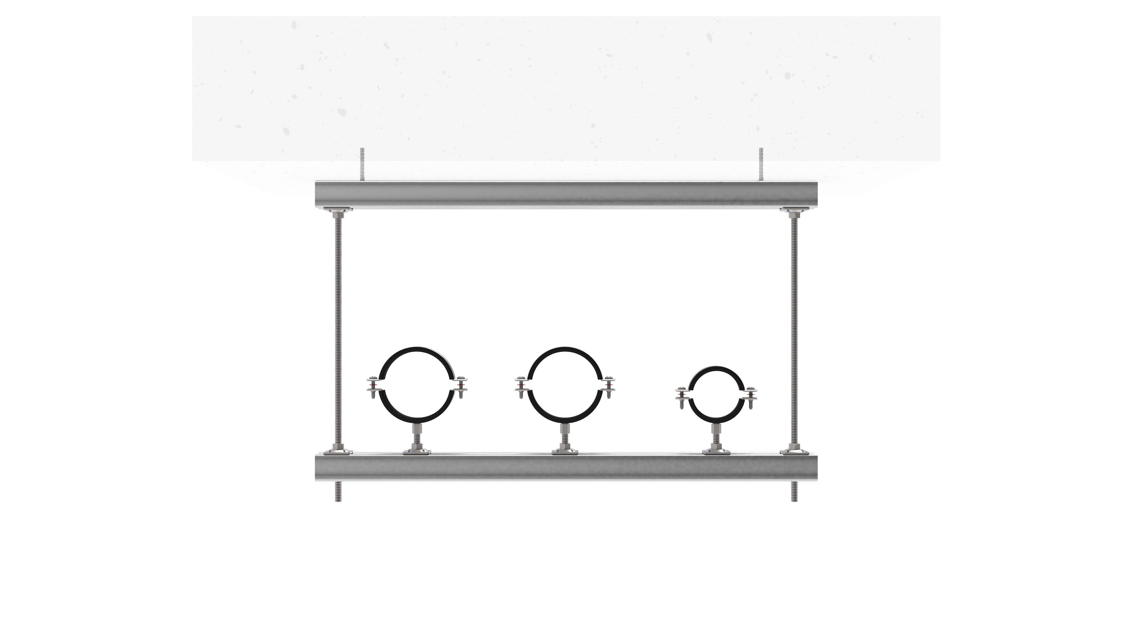
3 Point Load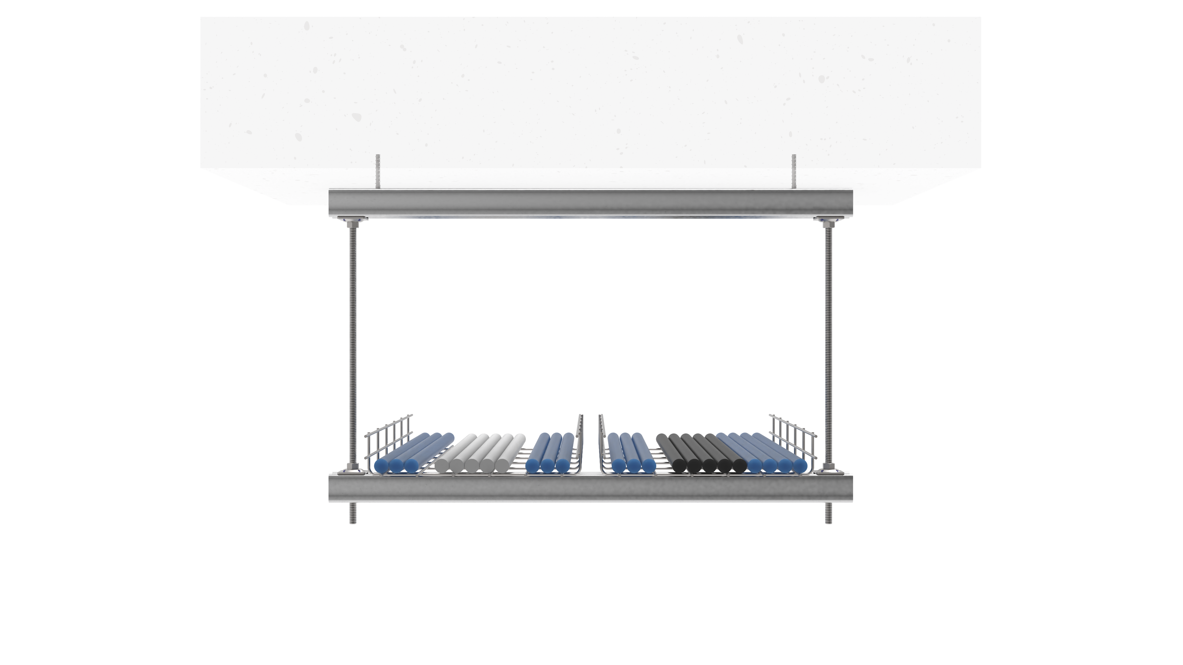
Uniform Load
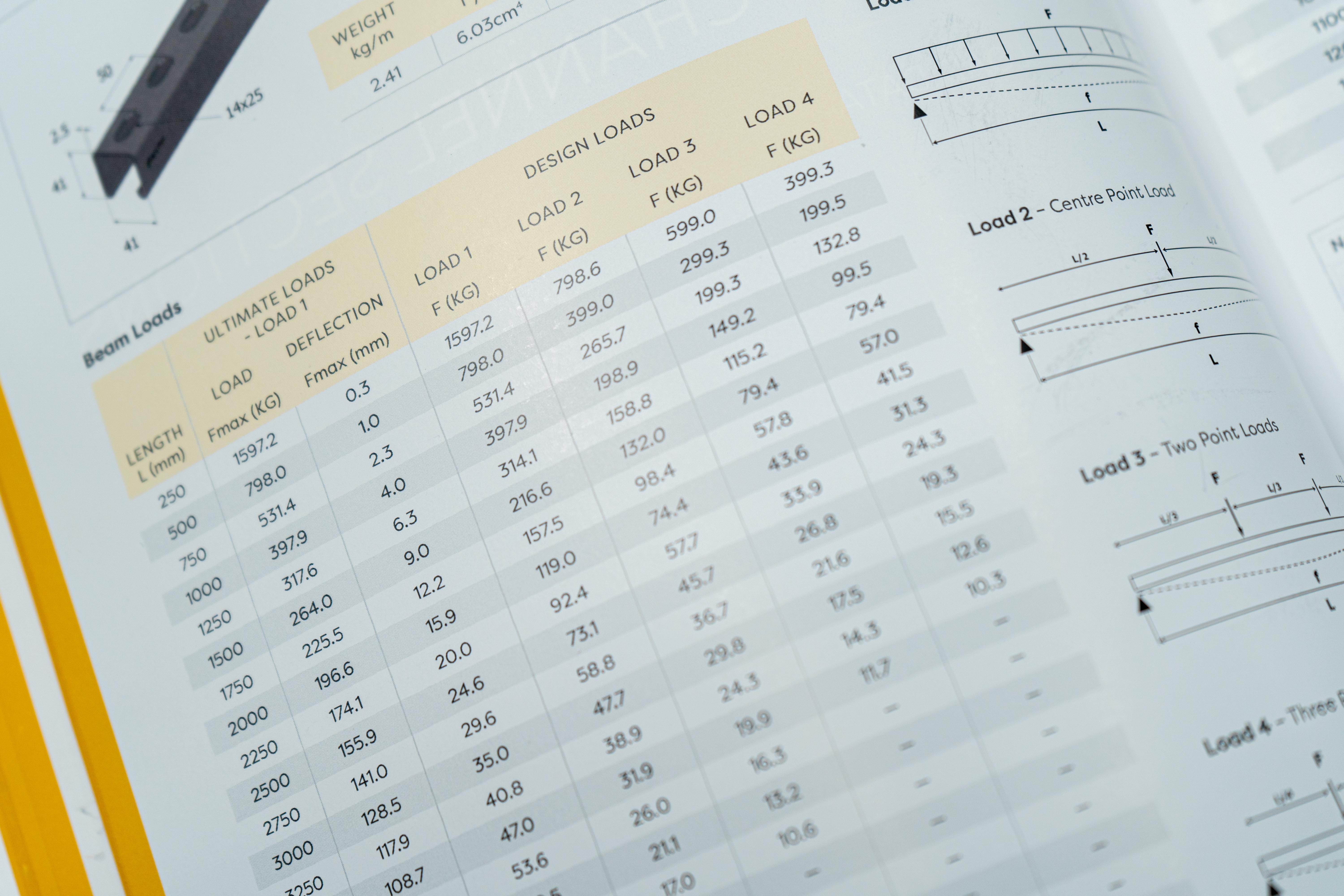
Ultimate Load vs. Design Load:
- Ultimate loads refer to the maximum load that a material or structure can bear before failure occurs. This limit is determined by stress and is typically accompanied by a safety coefficient, such as the commonly used factor of 1.6 according to RAL-GZ 655. Going over the ultimate load may lead to material failure due to exceeding its yield strength.
- Design loads, on the other hand, represent the maximum load limited by deflection. The industry standard safety factor for design loads can be specified, such as L/200 for simply supported beams. If the design load is surpassed, the material may exceed its deflection limitation.
Worst-Case Load:
A "worst-case load" refers to the maximum expected load or force that a structural element, such as a bracket, may experience under specific conditions. This concept is often employed by Design Engineers when designing bracketry for scenarios where complete information about the load distribution is not available. Another useful application is to determine whether the worst-case brackets are safe, according to which we can accept that similar cases that are less severe will be safe as well.

Maximum Stress and Maximum Deflection:
- Maximum Stress: The yield strength of a material. It is essential to stay within this limit to prevent permanent deformation or failure.
- Maximum Deflection: The degree of displacement or deformation under a load. Calculating and controlling maximum deflection is crucial to avoid structural issues and ensure functionality.
The Significance of Purlin Load Calculations:
Purlins are vital components in structural frameworks, especially in roofing systems. The proper assessment of purlin loading is paramount as it directly influences the integrity and stability of the entire structure. Failure to accurately calculate these loads can lead to structural instabilities, compromising the safety and longevity of the building.

The Challenges with Purlin Load Calculations
M&E contractors often grapple with the complexities of purlin loading calculations due to several factors. One major challenge lies in the fact that purlin capacity is usually given in area loads rather than point loads. This presents a puzzle for contractors, requiring them to decipher the equivalent service load to assess the utility of the design load on purlins accurately.
Unlike point loads, which act at a specific point in a structure, area loads represent the force applied over a specific area, making them a more abstract concept than point loads. In the context of purlin loading, this can be confusing for contractors as they need to translate these area loads into a point load equivalent for precise calculations.
This conversion from area loads to point loads involves understanding the distribution of the load across the purlin section. The challenge arises from the need to reconcile the continuous nature of area loads with the discrete nature of point loads. M&E contractors must grapple with questions like: How does the weight distribute along the length of the purlin? What is the equivalent concentrated load that accurately represents the impact of the area load on each purlin?
Furthermore, the intricacies of the formula involved in calculating equivalent service load can be daunting. Understanding the variables, such as point load on purlin, service spacing, and purlin centres, demands a nuanced understanding of both engineering principles and mathematical concepts.
How to Perform Purlin Load Calculations:
Calculating purlin loads involves determining the equivalent service load on each purlin. The following step-by-step guide outlines the process:
- Identify Point Load: Determine the point load being exerted on the purlin from the suspended supports. This is a crucial parameter in the load calculation process. Note that this should be in Kilogram.
- Gravity and Conversion Factor: Utilize the acceleration due to gravity (9.81 m/s²) and a conversion factor (10^-3) to convert the point load from kilograms to kilonewtons, aligning units for accurate calculations.
- Service Spacing and Purlin Centres: Define the support spacing, the distance between each mounting point along the purlin - and the purlin centers, the distance from one purlin to the next. These parameters are essential for understanding how loads are distributed across the structure.
- Apply the Equivalent Service Load Formula:
The formula for calculating the equivalent service load is:
Equivalent service load = (Point load on purlin * 9.81 * 10-3) / (Service Spacing * Purlin Centres)
Where:
- Point load on purlin is the weight per unit length applied to each purlin, in this case, 9.5kg every 1.454m.
- 9.81 is the acceleration due to gravity in m/s²
- 10-3 is the conversion factor to convert from kg to kN
- Service spacing is the distance between the purlins. [1454mm]
- Purlin centres are the distance between each purlin. [1600 mm]
- Using the given values, we can calculate the equivalent service load on the purlins to be 0.036kN/m².
-Dec-11-2023-03-48-12-5717-PM.png?width=654&height=254&name=MicrosoftTeams-image%20(2)-Dec-11-2023-03-48-12-5717-PM.png)
(Red shapes are the purlin sections going forward to back. Black line are the header rails going left to right.)
5. Evaluate the Results:
Compare the calculated equivalent service load with the design load capacity of the purlins. If the calculated load exceeds this capacity, adjustments such as increasing profile size or revising bracket spacing may be necessary.
Conclusion
In conclusion, M&E contractors stand to gain significant advantages by mastering engineering principles and terminology. A solid understanding facilitates improved communication with engineers, architects, and stakeholders, fostering collaboration and reducing misunderstandings. Moreover, it equips contractors with enhanced problem-solving capabilities and adaptability on the job, enabling them to navigate complex projects with efficiency. Furthermore, this knowledge also serves as a catalyst for continuous learning and professional development, crucial in a rapidly evolving field, ensuring M&E contractors remain at the forefront of innovation and industry advancements.