
.jpg?width=451&height=381&name=Pipe-bridge-blog-featured-image-compressor%20(1).jpg)
Dario Teixeira, Engineering Design Manager at MIDFIX discusses one of his projects where we designed a pipe bridge for a WTW Bio Energy Plant in Derby. Dario summarises the challenges we faced and how we overcame them. Our brief was to engineer and fabricate structural frames to support mechanical and electrical services at the site.
Our client’s requirements were:
- A main pipe bridge measuring 15m span and 10m height
- The frame had to support a service load of 2,800kg
- The structural frames should be engineered according to Eurocode and British standards
- Prefabricated for quick installation on site
- Main structure had to resist against wind load
- Structural support to be a hot dip galvanized material
- The structural frame and components should be a versatile system and adjustable on site
- Reliable delivery service
Our Challenges
Our technical challenges encompassed:
- Designing and selecting a frame system which met all our client’s requirements
- The max span and height of the bridge became an issue, the preferred frame system for the bridge only reached a maximum beam length of 6m.
- Ensuring that all bending, shear and tensile or compressive stresses are below the overall structural capacity.
- Ensuring structural stability considering the 10m height clearance against wind loading.
- Prefabrication and site delivery in a short-timescale.
Our Solution
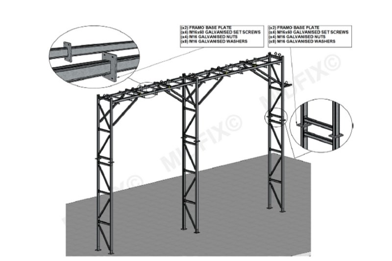
Our preferred solution was using Framo as the main structural frame. Framo is versatile and it offers flexibility when using a compact range of off-the-shelf components. The semi-rigid connections, beam-beam, beam-column or column-base plate were secured and assembled using M10 threaded forming, shake proof fastenings. The steel base plates were fixed to the concrete floor using M16 bolts.
We overcame the beam span limitation by using Framo base plates at the end of each beam/column connection, the plate acted as a splice connection to reach the required beam length as depicted in the image below.
Engineering Approach
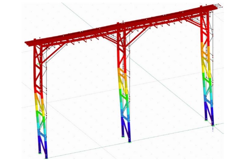
The structural frame was modelled and analysed prior to manufacture. This was a semi-rigid frame system and had to allow for some flexibility in structural connection, the beam moments are reduced but can generate a significant deflection on the structural members. Therefore, the connections should be able to transmit bending moment from beam to column with some degree of rotation.
As this was a lightweight structure, we paid close attention to the response of the structure to wind. From this analysis, we incorporated diagonal bracings to tie-up the structure longitudinally and transversely.
An ultimate limit state check was performed based on Eurocodes for each structural component. This verified the overall structural stability.
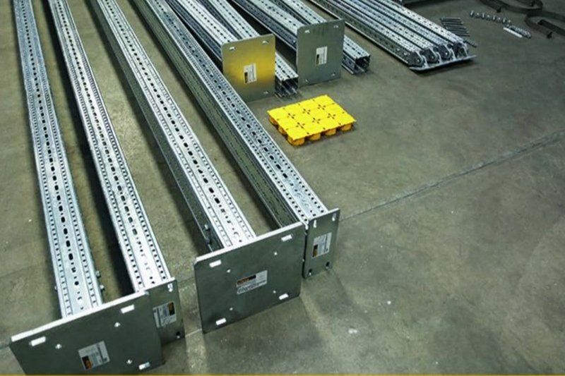
Prefabrication
We handed over the final fabrication drawing to our workshop. Before commencing the fabrication of the pipe bridge, the fabricator and design engineer ensured the following:
- Double check the list of components and their availability
- Ensure that all necessary tools and equipment are available and ready
Finally, the bridge was fabricated in sections, labelled and delivered to site for installation.
Delivery and Installation
As well as having our own FORS accredited fleet of vehicles, we have long term partnerships with some of the UK’s leading logistics providers to ensure that goods are delivered to customers on time.
We can undertake an engineering site observation to inspect external structural elements at any stage of the project. After the site observation, we produce an engineering report. This includes the objectives, any testing and compiled data, and a summary of the results and our recommendations.
Do you have similar project challenges? Contact MIDFIX today to speak to our sales team.